- This topic has 0 replies, 1 voice, and was last updated 5 years, 10 months ago by
 CLOC-Admin.
- Topic
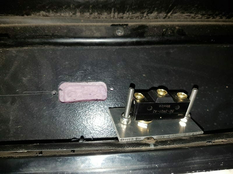
- CLOC-AdminThe limit switch for the slide.
Hope to keep the seals from being flatten and the flanges around the outside of the slide from bending.
The micro swtich is connected to a forward/reverse relay…….can’t believe I don’t have a picture of it : )
The plastic is threaded so depth of the micro switch can be adjusted with the screws.
Also insulated behind the plastic panel below the slide.

If you look closely at the bottom corner where the slide seal ends. The little bit of green/white are wires on the inside of the trailer…..be a good mouse hole….have to seal that up.
Posted: 8:56 PM – Jan 24, 2018Control panel. A hinge on this side allow access to the back.Posted: 10:45 PM – Jan 27, 2018The reversing relay for the slide. The slide motor is 25FLA. The breaker mounted in the side of the box is 30amp.There is 6ga from (protected by a 50amp breaker) the battery bus bar to the relay and 10ga from the relay to the motor.
Posted: 11:24 PM – Apr 03, 2018This is were the front pass through floor will be cut to access the 900Ah battery compartment.The grey box on the far side is the junction box for the “manual transfer” switch….with no onboard generator couldn’t see why we needed a ATS.
Red and yellow (1 ga) wires are for 1.3Kw solar.
900Ah battery bank below the front pass though floor
A Progressive EMS moved into a new home and a terminal block for a 50 amp/3000w pass through inverter
Synoogy NAS (Network Attache Storage) on my custom suspension system that (fingers crossed) will mitigate vibration/shock from damaging the hard drives
Thsi is below the washer/dryer.
Neg buss bar and copper mounting blocks for a Victron shunt/BMS.
4 – Blue Sea (300amp ea) battery switches connected with a 1/2″ x 1 1/2 (900amps) copper bus bar.
Each of the 2x6V (225Ah) battery banks will be connected to ( with 4/0 wire) one of the battery switches. This wlll allow each 2x 6V bank to be charged and equalized separability……or isolated if a battery fails.
Posted: 9:54 PM – Apr 10, 2018I kept the original lighting and wiring with combined red brake/signal tail light but I also ran new wring with the brake lights separated from the signal lights. The trailer now has 3 amber signal lights on each side and 4″ amber signal lights in the bumper. This is the terminal strip and the neg. bus bar where all the wiring comes together. This is in the front closet above the pin box. Still to go are the 100 amp charging wires from the truck.Below is the back wall in the front storage compartment.
I wanted to increase the battery capacity and keep the 4/0 cable lengths to a minimum.
Also wanted to make it easier to upgrade to (not convinced it is the way to go at this time) lithium. Thus the reason for moving the batteries (insulated with 2″ XPS) inboard and choosing an inverter with 120A charging capacity.
The battery switch assembly shown previously will be located at the bottom middle.
The run from the batteries (cables are the same length) to the battery switches is 3′. From the battery switches to the Victron is 2′
The plywood on the left and right are doors
Top left are switching breakers for:
4 x 70A -Bigfoot pumps
1 x 60A – House
1 x 50A – Slides
1 x 30A – 7gpm@60psi Water pump
1 x 100A – Truck charging
2 x 30A – 400C Viair air compressors
1 x 30A – Front SlideBelow the breakers is the Victon 3000/120 Inverter. There will be a 400A fuse on the back of this door for the Victron.
On the right door are 2 x 150/100 Victron solar controllers…holes in the doors are to improve cooling
25A (input) switching breakers are above the 120A (output) breakersWith the doors closed there are no exposed terminals that may have something fall against them while towing.
Posted: 10:28 PM – Apr 26, 2018There are 3 shore power plugs 50amp front left, back left and a 30amp front right. All are protected with GFI breakers. This means the whole trailer is GFI protected.Had to extend the bottom of the 50amp boxes to fit the GFI breakers…not ideal.
All the 50amp wiring was upgraded from 8ga to 6ga. I was concerned NMD may get damaged so I used Teck cable from the breakers to the 50amp receptacles.

eWith the 100amp charging from the truck we can power the fridge with AC instead of propane while traveling ( & sometimes while camping on solar) but I didn’t want to leave the 3000W inverter on more than necessary so I added an inexpensive 600W sine wave inverter.
The 600W is set up with receptacles close to the TV, propane fridge, WIFI router and Synology NAS. A 15amp electronic (quiet) transfer switch is between the 600W & House Service or items can be manually switched as the receptacles are next to each other.

Posted: 3:33 AM – Apr 27, 2018I was wondering about your 100 amp charging from the truck? My understanding is that the truck alternator only charges when it sinces that the truck batteries need charged.I have thought of installing a second alternator that would be only for the trailer batteries. But it it would require a separate wire from the truck.
Posted: 3:54 PM – May 01, 2018DandK-Travelers wrote:I was wondering about your 100 amp charging from the truck? My understanding is that the truck alternator only charges when it sinces that the truck batteries need charged.I have thought of installing a second alternator that would be only for the trailer batteries. But it it would require a separate wire from the truck.
A separate wire is required. In my case I’ve run 4ga but I may replace it with 1ga or 1/0.
Batteries are similar to water tanks that are connected together with a pipe.
When the tanks are full no water flows through the pipe.
As water is drawn from one of the tanks water flows though the pipe. As the level of the tank drops the flow of water through the pipe increases but even if the tank is draw down to 1/2 there is only so much water that will flow through the pipe.
Posted: 9:13 PM – May 25, 2018The Blue Sea rotary transfer switch. …looks like RV wiring!https://www.bluesea.com/products/8361/A … OFF_3_Pole
Shore power inputs to the switch are:
50 amp back left
50 amp front right
30 amp “Smart Plug” front left.
http://smartplug.com/portfolio-item/30- … -assembly/Each of the inputs is protected by a GFI breaker
Box for the Progressive EMS is finished. Wire is 6 ga.
Posted: 11:23 AM – Jun 26, 2018Installed USB plugs on both sides of the bed while rewiring the bedroom slide. The light maybe great for plugging in at night but it may be too bright.Posted: 11:27 AM – Jun 26, 2018Alloy wrote:The limit switch for the slide.Hope to keep the seals from being flatten and the flanges around the outside of the slide from bending.
The micro swtich is connected to a forward/reverse relay…….can’t believe I don’t have a picture of it : )
The plastic is threaded so depth of the micro switch can be adjusted with the screws.
Also insulated behind the plastic panel below the slide.
If you look closely at the bottom corner where the slide seal ends. The little bit of green/white are wires on the inside of the trailer…..be a good mouse hole….have to seal that up.
These work 100%. An excellent modification that will prevent the flanges around the slide from bending.
B.W.Gentry
Owner/Admin
2007 Carri-Lite XTRM5
Breckenridge, TX


- You must be logged in to reply to this topic.